regarding this table:
is the solution implemented using this table?
I find it problematic because it doesn’t wait for the clock to go up so the information can be updated.
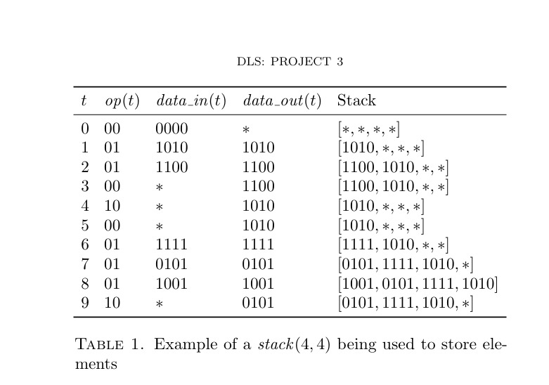
The expected functionality of the stack is indeed as shown in this table. The i'th clock cycle (denoted in the table as t = i) starts once the clock rises, and the inputs need to be held constant for some time before and after this rise. Perhaps it is easier to understand the table if you think of the entries of the t column to correspond to a time t = i + \epsilon, where the clock rises exactly at t = i.
if the data is stable in the time between 1-2, it should enter the stack and be shown in data out between 2-3 / the table is off by 1 for the stack content and for data_out
The output updates as soon as the clock rises and remains at that value till the next rising edge of the clock. The only constraint on the inputs is that they should be at the appropriate value when the clock rises. They need not be stable for the entire previous clock cycle.
For example, if you’re looking at the clock rising edge at t = 2, then
- \mathit{op}(t) = 01 for t \in (2 - \varepsilon, 2 + \varepsilon)
- \mathit{data\_in}(t) = 1100 for t \in (2 - \varepsilon, 2 + \varepsilon)
- \mathit{data\_out}(t) = 1100 for t \in (2,3)
The state transition occurs at t = 2, based on the value of the inputs at that time.